Removal of the Angle Iron Reinforcements from Land Rover body sides
by Clive MacDonald Smith
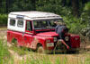
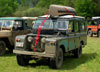
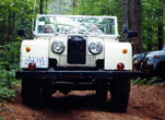
This article pertains to Land Rover military built to "Combat Specification" Mks 8, 8/2, (SWB) - 9, 9/1, 11, Series 3 (LWB) 12 volt and 24 volt models.
The Land Rover Mk 10 also had angle irons but only one batch was made prior to the introduction of the Air-Portable in 1968 and I dubt if any have made it to North America. Part of the specification of the Combat Land Rover is that it has lashing rings in the rear cargo body, these lashing rings have to be securely fastened to the body, two bolts pass through each ring into captive nuts mounted on angle irons under the body floor and wheel arches.
It is these angles which are made of mild steel that react with the aluminum panels of the rear body aided by water and salt sprayed up by the wheels and after a number of years corrode through the body sides. See drawing three A1. The angles in the rear toolboxes need not be removed unless desired as they are not exposed to the splash (LWB only) See drawing three E.
Actual Removal: Start by drilling out the remains of the "pop" rivets on the outside of the body (drawing one and two A) on LWB models only drill the rivets forward of the rear wheelarch. Next get into the back of the vehicle with a 7/16 AF ring spanner and remove the rings by undoing the bolts that secure them. You may need to chip away layers of paint to get to the bolts (two to each ring). If the rings do not want to come out when the bolts are removed tap them lightly with a hammer. See drawing three B (In LWB, only the front two rings need be removed on each side)
Next step having removed the rings you will see some "pop" rivets (drawing three A). There may be two, one at each end of the angle iron, or four equally spaced along it, depending on the age of the vehicle. These should be drilled out if they have not corroded away. Do Not, I Repeat Not drill or chisel any dome rivets (drawing three C) as these hold the aluminum body supports and must not be removed.
By this time you should have heard a cloud clunk as a 30 inch approx. piece of iron falls to the floor in the case of a LWB, on a SWB the irons come in three short lengths of about 10 inches. If at this point the said angle is not forthcoming and you have followed these instructions, get the hammer and a 1/4" pin punch or similar and place it down one of the bolt holes and give it a shape tap. This will dislodge the iron.
You will be left with some holes to fill. Put new aluminum"pop" rivets in the rivet holes and where the bolts come out, put new bolts or grommets, if you wish to refit the lashing rings for use, I suggest fitting aluminum angle 1/8`thickness and stainless steel bolts.
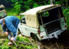
Drawing Three dotted line at A shows the outline of the angle iron, to examine it in detail before removal park the vehicle on level ground and chock the wheels. Then lie underneath just in front of the rear wheel and look up the inside of the body side where the upright joins the wheelarch and you will see it, if it is not buried in mud.
To remove rings and brackets at drawing three D proceed as before except that the three "pop" rivets on the floor are put in from underneath and you will only see their tails from inside the vehicle. These may be chiseled off or if badly corroded when the other bolt holts and tap them as before to remove the angle iron which are approx. 6 inches long by 3 inches deep. There are two of these brackets on a LWB and four on a SWB. If these brackets are very badly corroded, they have been known to take out a piece of the body the same size as themselves when they fall, requiring quite a major plating job to cover the hole, with aluminum of course.
Whilst I am writing, I would like to thank Ottawa Valley members who invited me back to their rented house for supper during the 1994 British Invasion at Stowe Vermont and yes I do agree "Bates" er Mr. Pilgrim does make the best Spaghetti Sauce!! All the best for 1996.
Notes: Drawings to be scanned in at a future date. If you really need them, contact a member who would have a copy of the newsletter