|
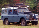
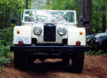
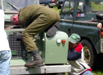
Series Land Rovers
Land Rover Electrical Wiring Diagrams
Series One 1948 - 1958
Series II 1958-1961
Series IIA 1961-1970
- Positive earth, Petrol
- Positive earth, Diesel
- Positive earth, Diesel with combined electrics
- Positive earth, Forward Control
- Negative earth, Petrol
- Negative earth, 6 cylinder
- Negative earth, Diesel
- Negative earth, Petrol, headlamps in the wing
- Negative earth, 6 cylinder, headlamps in the wing
- Negative earth, Diesel, headlamps in the wing
- NADA, Negative earth
- Forward Control, Petrol, negative earth
- Forward Control, 6 Cylinder, Negative earth
- Sorward Control, Diesel, Negative earth
- Trailer Flasher unit, Negative earth
Series III, 1971 - 83
- Circuit Diagram, 40 amp generator
- Circuit Diagram, 12 volt models, not fitted with rear guard fog lighting system
- Circuit Diagram, 12 volt models, fitted with read guard fog lighting system
- Circuit Diagram, 24 volt models
- Circuit Diagram, 24 volt models with transistorised charging system
- Circuit Diagram, 24 volt models with transistorised charging system & rear guard fog lighting system
- Circuit Diagram, 24 volt models, 90 amp generator
- Circuit Diagram, 24 volt models, 90 amp generator with transistorised charging system
- Circuit Diagram, 3/4 ton, 109 24 volt LR selenoid operated fuel cut-off valve
Series III diagrams contributed by Lee Jones
|
| |
|
Copyright Dixon Kenner, 1995-2011. Last modified March 15, 2005.
Comments? Send mail to Dixon Kenner or Benjamin
Smith
Site Designed and Created by Bill Maloney |
|